This post is a continuation of “Campus High Level Design – Sample Physical Topology, Part 1”.
The example depicted in the first part was a simple, 2 Tier, Layer 2 Leaf & Spine topology. The actual architecture for a production network would be dictated by a number of factors. It is possible that the number of Edge cabinets & uplinks, or distance to the Core etc. dictate the use of an Aggregation/Distribution Layer between Core and Access. This layer will then aggregate all Edge/Access Switch/Stack uplinks, while presenting its own uplinks into the Core. Similarly, it might be desired to curtail VLANs/broadcast domains locally at the Access, and use Layer 3 & Routing protocols between Access and Northbound tiers (Core, Aggregation) – instead of using Layer 2 and STP, to manage redundancy in-between the layers. The preferences and requisites will be dictated by the particular implementation.
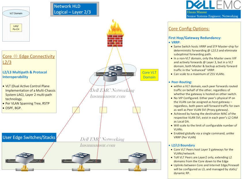
The logical topology that pairs with the physical one in the previous post, is fairly straight forward.
- The 2 tier topology has the VLAN SVIs hosted in the Core. it therefore facilitates a wide broadcast domain.
- In the Core, the gateway of first hop redundancy can come by way of either VRRP, or peer routing. Peer routing is simpler to implement, and scales (total VLANs) better than VRRP.
- The links between access & core remain layer 2, making use of Layer 2 multipath via VLT, in the Core. Dual uplinks to the Core from the Access switches/stacks will be in a LAG group, and therefore, active-active.
- Access Stacks could scale up to 9 units in a single stack if using N-Series Switches. With S-Series, the number would stop at 6.
- While 2x10G uplinks from the Access stacks is very common, it is good to nevertheless remain mindful of desired over-subscription ratios, and the kind of traffic/profile passing through the switches. Capacity between access/core can be augmented by adding more links to the LAG bundle presenting to the Core.
- Spanning tree would still be a part of the configuration.
- Examples of other Protocols, Features & Services which will need to be considered include Access Control, QoS/CoS, VOIP/Lync, dot1x etc.
The following table captures a high level overview of typical switches used in such deployments. Other options exist, for e.g. the C-Series Chassis is a comprehensive campus solution based on DNOS 9.
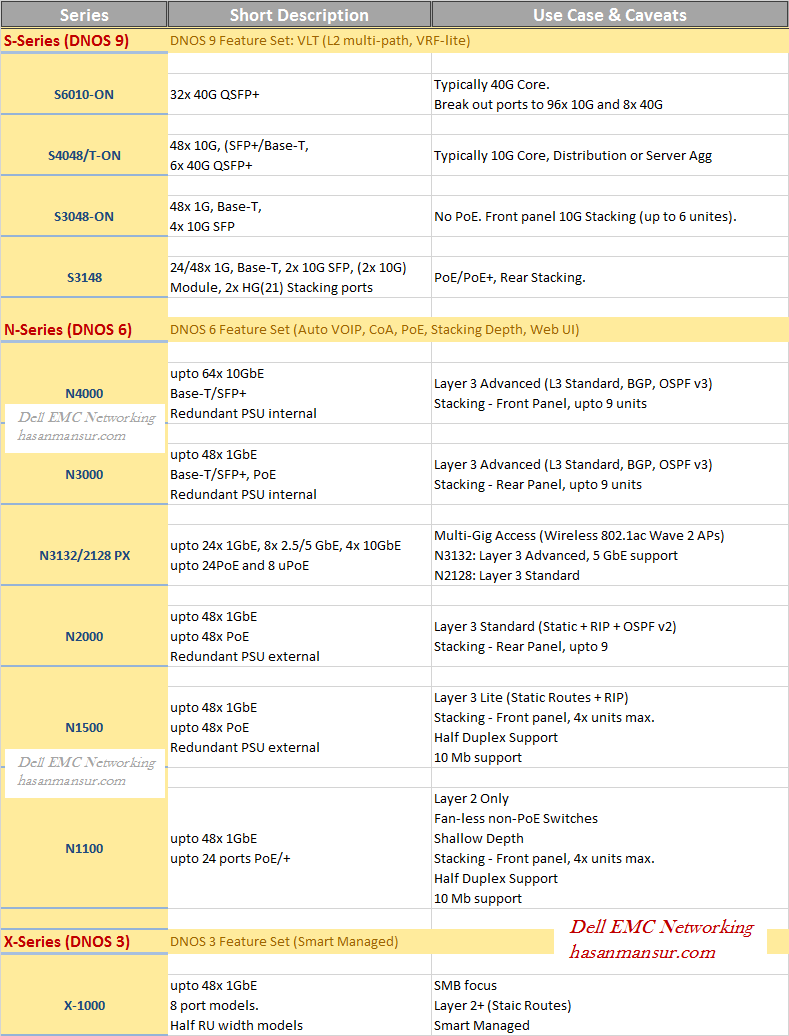
.
