
Some time ago, I had compiled some Notes to assist in explaining BCF Firewall Service Insertion to an audience from a Traditional Networking background. The details are fairly easy consumption. The Firewall may be hosted in the same segment/VLAN, or in a dedicated Tenant – Re-directing the traffic to the firewall in itself is straight forward.
There are multiple ways BCF and firewall services can be deployed to provide network and application security. The following table is an aid I compiled to simplify & draw a parallel with a traditional, non-fabric setup/NOS.
|
1 |
BCF L2 Fabric. VLANs Mirror on FW and Switch. VLAN Gateway on FW. |
|
2 |
BCF L3 Fabric. VLANs Mirror on FW and Switch. VLAN Gateways on Switch. Redirect to FW within same VLAN. |
|
3 |
VLANs/Gateways terminate on Switch. Single Edge VLAN between FW and BCF. Default/Static route in each direction. |
|
4 |
Multi-Tenant – Within Each Tenant, Dedicated Edge VLAN and physical/logical links up to the FW |
|
5 |
Multi-Tenant – System Tenant for Inter-Tenant Traffic & Policy. Separate Tenant for Firewall Services. |
Details for the first two options are as follows, the rest of the options will be covered in subsequent posts.
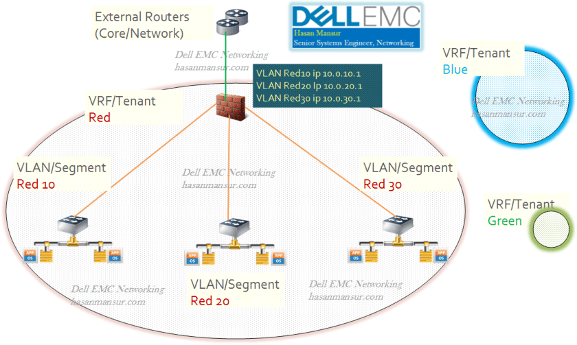
BCF is L2 Fabric; L3 Routing on FW (intra tenant). VLANs mirror on BCF and FW. Gateway on FW.
The firewall links to BCF trunk respective VLANs. The firewall hosts the SVIs which serve as gateways for the respective VLANs.
For Comparison with traditional NOS,
- The switch has VLANs 10, 20 and 30
- All VLANs may have local SVIs on switches. These appear to be cosmetic, and not used as gateways.
- All VLANs have SVIs on the firewall, which are the actual gateways for all VLANs.
- Firewall has links to Edge/Core Routers.
- There is a Trunk link between Firewall & Fabric, carrying respective VLANs.
- All traffic hits the firewall VLAN SVI gateways. After firewall treatment, traffic could be external routed or internal inter-VLAN routed.
- Thus, while switches have VLAN SVIs, the intervlan routing does not happen because the traffic is first sent to the firewall before being either routed out of routed back into an internal VLAN.
- This is not ideal as it causes hair-pinning of the traffic
All VLANs have ip addresses on FW, which is the gateway for hosts on the VLAN.
Configuration from the perspective of the switch (Traditional/DNOS CLI)
Interface vlan 10
Name Red10
Ip address 10.0.10.2 /24
Interface vlan 20
Name Red20
Ip address 10.0.20.2 /24
Interface vlan 30
Name Red30
Ip address 10.0.30. 2/24
Interface port-channel 10
Description Trunk to Firewall
channel-member fortyGigE 1/49
channel-member fortyGigE 1/50
No shut
Redirect traffic to FW. VLANs Mirror on BCF and FW. GW on switch, next hop to FW ip on same VLAN.
For Comparison with traditional NOS,
- The switch has VLANs Red10, Red20 and Red30.
- The same vlans exist on firewall
- A trunk link carries all vlans between switch and firewall.
- All VLANs have an SVI on switch, and an ip address on the firewall.
- The gateway for each vlan is the SVI on switch
- Traffic received on each switch vlan interface (gateway)will be forwarded/re-directed to the firewall interface on that vlan.
- Post treatment, traffic is forwarded, as intended and defined on the firewall.

Configuration from the perspective of the switch (Traditional/DNOS CLI)
Interface vlan 10
Name Red10
Ip address 10.0.10.1 /24
Interface vlan 20
Name Red20
Ip address 10.0.20.1/24
Interface vlan 30
Name Red30
Ip address 10.0.30. 1/24
## Next-hop Red10 FW ip = 10.0.10.254
## Next-hop Red20 FW ip = 10.0.20.254
## Next-hop Red30 FW ip = 10.0.30.254
FW-insertion policy (Simplified)
(permit) Traffic received on vlan interface 10 (Red10), from any source to any destination, forward to next-hop FW ip for vlan Red10
(permit) Traffic received on vlan interface 20 (Red20), from any source to any destination, forward to next-hop FW ip for vlan Red20
(permit) Traffic received on vlan interface 30 (Red30), from any source to any destination, forward to next-hop FW ip for vlan Red30
—
Part 2 – Dell EMC Networking & Cloud Fabric – Firewall Insertion part 2
