
Continued from Part 1.
VLANs/Gateways terminate on Switch. Single Edge VLAN between FW and BCF. Default/static route in each direction.
For Comparison with traditional NOS,
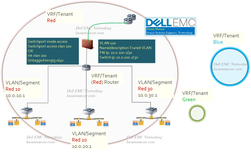
- The switch has VLANs Red10, Red20, Red30.
- All VLANs have local SVIs on switches. These switch SVIs are the gateways for all VLANs.
- There is an Edge/Transit VLAN (VLAN 100) between firewall and switch.
- Firewall has links to Edge/Core Routers.
- There is a default route on switch that forwards all traffic received on vlan interfaces, to FW trusted interface (10.0.100.1/30)
- The firewall will have route entries for all the subnets on the BCF, via next hop 10.0.100.2 /30(BCF trusted interface)
- After firewall treatment, traffic could be external routed or internal inter-VLAN routed, by being sent back to 10.0.100.2
Configuration from the perspective of the switch (Traditional CLI)
Interface vlan 10
Name Red10
Ip address 10.0.10.1 /24
Interface vlan 20
Name Red20
Ip address 10.0.20.1/24
Interface vlan 30
Name Red30
Ip address 10.0.30.1 /24
Interface vlan 100
Name Transit VLAN
Ip address 10.0.100.2 /30
ip route 0.0.0.0/0 next-hop 10.0.100.1
##Next-hop FW = 10.0.100.1
##FW-insertion policy
(permit) Traffic from any source to any destination, forward to next-hop FW.
(Permit) Traffic received on FW-trusted vlan interface, from any source to any destination
Inter-Tenant Traffic – Dedicated Firewall Edge VLAN per Tenant, Dedicated physical/logical links from FW to each tenant
For Comparison with traditional NOS,
- The switch has multiple tenants.
- Each tenant has VLANs 10 and 20, in their own respective ranges.
- Each tenant also has a firewall vlan. This is an Edge/Transit VLAN between firewall and switch.
- All VLANs have local SVIs on switches. These switch SVIs are the gateways for all VLANs.
- Firewall has links to Edge/Core Routers.
- There is a default route on each tenant, that forwards all traffic received on vlan interfaces, to that tenant’s next hop FW int (Red: 10.0.100.1, Blue: 172.16.100.1). Thus, each tenant’s traffic is forwarded to its own firewall.
- The tenant dedicated firewall will have route entries for tenant subnets. The next hop it uses will be switch SVI on FW vlan for that tenant.
- After firewall treatment, traffic could be external routed or internal inter-VLAN routed.

Configuration from the perspective of the switch (Traditional CLI)
Ip vrf Red 1
Interface vlan 10
Name Red10
Ip address 10.0.10.1 /24
Interface vlan 20
Name Red20
Ip address 10.0.20.1 /24
Interface vlan 100
Name firewall Transit Red
Ip address 10.0.100.2 /30
tagged po-ch 10
##Next-hop FW = 10.0.100.1
##FW-insertion policy
##On Tenant Red Logical Router,
##(permit) Traffic from any source to any destination, forward to next-hop FW.
##(Permit) Traffic received on FW Transit-Red vlan interface, from any source to any destination
—
Ip vrf Blue 2
Interface vlan 10
Name Blue10
Ip address 172.16.10.1 /24
Interface vlan 20
Name Blue20
Ip address 172.16.20.1 /24
Interface vlan 101
Name firewall Transit Blue
Ip address 172.16.100.2 /30
Next-hop FW = 172.16.100.1
tagged po-ch 20
##FW-insertion policy
##On Tenant Blue Logical Router,
##(permit) Traffic from any source to any destination, forward to next-hop FW.
##(Permit) Traffic received on FW Transit-Blue vlan interface, from any source to any destination
———-
