
Why:
Business Continuity.
Before discussing the different types of connectivity, it would be useful to have a quick look at the different traffic profiles within a DC.
Traffic Profiles & flows in the DC
There are a variety of traffic profiles & flows within the DC.
- East-West traffic demands a large Layer 2 domain with L3 boundary hosted in the core, to allow the broadcast domain to stretch between the racks. This could be seen in small/medium 2-Tier deployments, with the Core hosting the VLAN SVIs and Access switches providing edge ports and Layer 2 extension. Typically, east west traffic patterns manifest in
- Server to Server traffic e.g. app <> database, vMotion etc.
- Server to storage traffic.
- North-south traffic could dictate small broadcast domains, with the gateways hosted at Access or First Hop. This would manifest in ToR switches hosting the respective SVIs, as typically seen in the aggregation layer of a traditional 3 tier design. Typically, North-South traffic patterns manifest in
- Client to Server traffic.
DC interconnect itself could be Layer 1, 2 or 3. We will look at it in more detail further down the post, but by way of a quick overview,
- Layer 1 DCI may be seen in FC interconnects.
- Layer 2 DCI is typical for VM and IP address mobility. (Care should be taken with regards to Traffic Trombone, which we will briefly look into, below)
- Layer 3 DCI could be seen where the payload is iSCSI, or in database transaction replication.
Let us look at the Tromboning aspect of a Layer 2 DCI.
Layer 2 DCI & Tromboning
Tromboning happens if for e.g. a VM migrates from its original (e.g. DC 1) to a second (DC 2) location. While It comes up with the same IP address and VLAN membership as before, its gateway however, continues to be in DC1. So now, the traffic from the node has to travel back to site A gateway, to route outwith. (Additionally, its subnet could/would also keep getting advertised from DC 1).
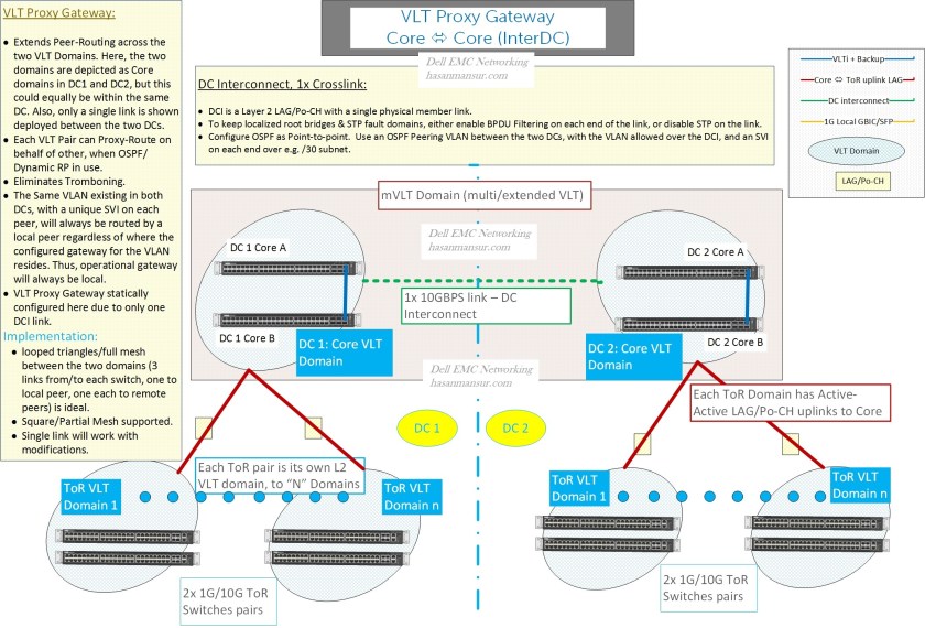
VLT Proxy Gateway
This is where Gateway Localisation comes into the picture. Dell EMC Networking’s Proxy gateway achieves this by having one VLT pair , proxy-route on behalf of a second VLT pair. Proxy Gateway happens between VLT domains, as opposed to within.
When this function is applied within a DC, it is known as Peer Routing – The two Peer switches will proxy-route on behalf of each other. The alternate to peer Routing will be VRRP. The considerations in choosing one over the other (within a DC) include:
- VRRP supports 255 VLANs, Peer routing scales to the max supported (4K)
- Peer Routing takes a single global command to enable. VRRP might take 3 or 4 commands per VLAN stanza (VRRP-group, priority, Virtual IP, advertise interval etc.)
Note again – Peer Routing vs. VRRP is a choice executed within a DC. VRRP is not a consideration for use with Proxy Gateway between the DCs (The two are mutually exclusive).
Back to proxy gateway – All 4 switches, 2 each per VLT domain, in 2 VLT domains – can proxy-route on behalf of each other. For a given VLAN which stretches between two DCs – While the VLAN exists in both DC1 and DC2, for any given host in a VLAN, regardless of which DC it is located in and which gateway IP address (from between the four L3 boundary switches, a VLT pair per DC and two in total) it uses, its traffic will always be routed by the L3 boundary switch which receives its traffic. This becomes particularly attractive with workload mobility, movement and vMotion in mind.
In it’s respective CAM table, each peer creates a local destination address entry (in addition to its own MAC address) for the peer’s MAC address, which is how it ends up routing on behalf of the peer, regardless of whether the gateway points to the other switch. On the host, one can configure any gateway address from the ones being used by the peers on the respective VLANs.
There are caveats with the use of Proxy gateway, and questions to consider. for e.g. If the original gateway goes offline, the peer doing the proxy on behalf of the gateway will cease to answer ARP on gateway’s behalf. If a node needs to renew the ARP entry at that point, it will be without a gateway.
Over time, further enhancements and/or alternates to Proxy Gateway functionality may become available. e.g. A VRRP based solution using a VIP/VMAC default gateway on a given VLAN, between the two VLT domains in the two DCs, (similar to Cisco HSRP/extended subnet mode between DCs). ACLs on the LANe interconnect will restrict VRRP hellos/exchanges, similar to HSRP filtering that happens on the DCI.
The other available option/alternate to Proxy Gateway is the use of VRRP between the 4 switches in the 2 VLT domains – Note however, that this will not be an active Master per DC (with VRRP control frames filtered on the DCI), rather one master across both DCs (and the rest, slaves) – consequently, tromboning in this model will be applicable.
Also, one could configure Peer routing in one DC and VRRP in the other.
Going back to the discussion around DCI in general and Layer 2 DCI in particular, there are other challenges with L2 DCI, which result from the fact that the location of server/app may no longer be accurate as a result of move. Typical ways to get around it may include LISP, DNS redirection etc.
DCI Service Types:
A variety of DCI services exist. These include
- Layer 1 services like Dark Fiber/DWDM. Layer 1 services could be required by FC interconnects.
- Layer 2 Service Like Pseudowire, which is a P2P emulation. For a layer 2 DCI between two DCs, two pseudo-wires bundled together, in conjunction with L2 control packet filtering on the link (Localize STP topology) are a fine solution. However, be mindful of the multicast impact/replication support. (I will cover Pluribus Networks’ great Layer 2 Pseudo-wire Solution in a subsequent post).
- A quick mention of some third party solutions,
- OTV (Cisco) dynamically encapsulates L2 frames in L3 packets (on edge devices), all while keeping the L2 domains in the respective DCs, distinct. it also includes the concept of MAC routing, and uses IS-IS as control plane. OTV is however, hardware dependent (Nexus 7k)
- Another solution enhances VPLS, to enable support for Multi-chassis LAGs across the provider network, resulting in active/active links and load balancing.
- Layer 3 Service: The fault domains will be contained wihtin respective DCs. An example could be the Anycast model, where both sites advertise the same IP range. The DCs will be active-active – the location of traffic source will determine the DC the user is routed to.
……..Will continue in part 2.

Hi, thanks for your very useful information on Dell Networking stuff. Is proxy gateway still the only option for gateway localisation in Layer 2 DCI? I can’t find anything in User guide regarding Proxy Gateway configuration as i would like to test it in a lab.
Benjamin
Hi Benjamin
I am glad you have found value in content on this blog.
With reagrds to yoru query,
Proxy gateway is depreciated. for a single VLT domain, you can still make use of Peer Routing or VRRP , in conjunction with VLT.
For multiple VLT domains, you could use “Enhanced VRRP” as a replacement. this is Active Active VRRP, with gateway localization and routing at first hop, to avoid trombone. the User Guide shoudl cover this with examples.
I hope this helps. thanks for the message !
Hasan
Hi Hasan,
Thanks for your prompt response. I thought so already but I didn’t find good information / examples online. Dell does mention „ Migrate VMs across data centers with eVLT“ in the OS10 User Guide but not in detail if enhanced VRRP will be active-active when having multiple VLT Domains. Migrating VMs across a stretched Vlan between DCs with the ability to route locally and to prevent tromboning is my goal.
Hi Benjamin,
You are welcome. Your requirements should be met via VLT and VRRP, which in conjunction give you the multi-path and redundancy mechanism at L2 and L3.
So, Active Active & Route at First Hop will be addressed by Enhanced VRRP.