Continuing from where we left off in part 1, we will start with a look at some of the implementation details, before looking at Deployment types and modes.
Deployment Building blocks
We have already had a look at the components in the previous post. As discussed, there are 3 key components that make up the Silver Peak SD-WAN.
- Orchestrator – Manages all Appliances, and defined all Policy. It automatically detects appliances, but does need the admin/operator to manually approve each discovered device.
- Appliance (Dell EMC VEP, SP EdgeConnect).
- Cloud Portal – License Management.
Implementation
The building blocks that articulate the implementation, are as follows.
Labels:
Can be thought of as Interface Identifiers. Multiple interfaces can be grouped under the same identifier, and will therefore be treated identically.
There are two types of labels. LAN and WAN.
LAN labels are for Application traffic, i.e. traffic types (e.g. VOIP). WAN labels, are for Service Traffic, i.e. they identify the Network Service the WAN interface connects to. Traffic received on a LAN interface carrying a particular label, would be sent to a particular BIO (Overlay) and handled as defined. The WAN labels are used by Orchestrator and BIOs to determine the interfaces on various Appliances across the sites, which will be connected by the tunnels.
Deployment Profiles:
A key aspect of Automation. Instead of configuring each Appliance individually, we can create Deployment Profiles and provision a device by applying the respective profile. These are primarily, Configuration templates. They include configuration for interfaces, as well as the labels to be applied. Profiles do not contain IP Addresses, as these vary site to site. whenever an Appliance is added to the Orchestrator, an appropriate Deployment Profile can be applied.
Business Intent Overlay:
It defines details such as the interfaces used to create/terminate tunnels on appliance, and association/mapping of source LAN to WAN overlay networks. Which traffic matches a particular BIO is determined either by the label on the interface for incoming traffic, or by matching traffic to an access list. The BIOs manage WAN interfaces and network Service used for transmitting traffic, as well as thresholds & actions for Brownouts.

- Multiple BIO can be defined to create different set of Overlay Connections, for different sources of traffic, of different types. They are Dynamically created & maintained. Traffic can be auto routed and re-routed as network conditions change.
- Underlay can be different types of connectivity as well as different providers. Different providers can be tricky, and is recommended for pure internet (2 WAN connections) only.
- @ version 8.0, up to 7 overlays were supported
- Overlay Topology type could be Mesh or Hub & Spoke.
- Traffic Access Policy maps incoming traffic to an Overlay.
- Link Brownout Threshold defines the conditions under which a given physical link is no longer considered for transport. the conditions refer to aspects such as Loss, Latency and Jitter.
- Route Matched Traffic to WAN Port, defined the destination port mapping.
- Link Bonding Policy, as referenced in the part 1 of the Blog post, could be optimized for Availability, Quality, Through-put or Efficiency.
- In case of Overlay down, available Route Policy Fallback behaviour options are
- Pass-through shaped
- Pass-through unshaped
- drop
- Shaper Traffic Class allows the choice of the QoS traffic class which packets matching a BIO are placed in. By default, all traffic is placed in Class 1.
- The Boost license option was traditionally the WAN Optimization piece.
The Orchestrator auto-creates the Route Policies in response to the BIO configuration.
Policies
typically created by BIOs, can also also be created manually. All Policy Rules have Priority, Match Criteria, and Actions. These are organized under objects called “Maps”, and are of three types.
- Route Policies: the traffic should be sent to
- which destination
- via which tunnel
- sent as pass-through, or dropped etc.
- Optimization Policies: Is Wan Optimization to be applied? the details on
- TCP Acceleration
- Payload Compression
- Network Memory
- CIFS Acceleration
- QoS Policies: Bandwidth allocation for different traffic types. Works in conjunction with Shaper.
- BIOs would typically determine the traffic class a packet is placed in.
- QoS is used to treat exceptions to the BIO configuration. The Shaper provides a simplified way for Global QoS configuration. The Shaper’ allocates ten traffic classes. Four of these are present by default.
- Realtime,
- Interactive,
- Default, and
- Best effort.
- The system applies these QoS settings globally after compressing all the tunnelized and pass-through-shaped traffic, shaping it as it exits to the WAN.
- The QoS Policy’s SET actions determine two things:
- Traffic Class assigned to a flow
- Trust or Re-Mark, incoming DSCP markings for LAN + WAN QoS.
- Use the Shaper to define, prioritize, and name traffic classes. Then use the QoS Policy to assign packets to traffic classes for processing.
Deployment Types & Mode
I have tried to group the different elements under brackets, that would ease consumption of the information.
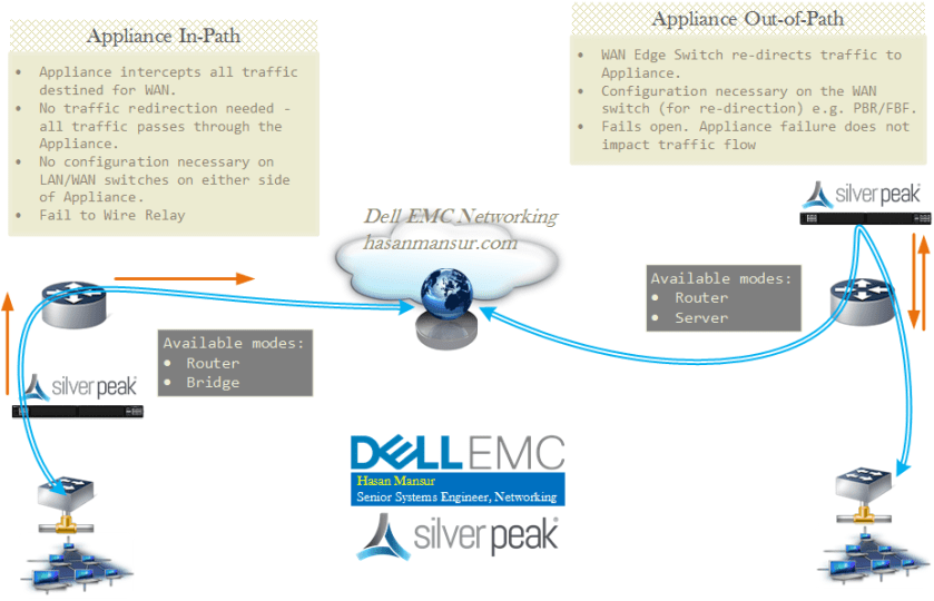
The deployment types are in-path and out-of-path. Within the context of in/out of path, the Appliance can be in the following modes:
- Bridge Mode is the easiest to setup, and consumes 2 to 4 ports. There is no out-of-path option for Bridge Mode – It can only be In-Path.
- Router Mode is suitable for more complex installs, and can be in-path or out-of-path. in-path is simpler of the two options. Needs at-least 2, and supports up to 6 interfaces.
- Server Mode is only available as Out-of-path. it uses mgmt0 port only.
Virtual Appliance are typically deployed out-of-path is Server or Router Mode, while Router Mode is the default for physical devices.
Let us have a look at the deployment modes.
In-Path/In-Line
Here, the EdgeConnect (or the VEP) Appliance is situated in-line, between the External WAN router and internal LAN switch. The Appliance intercepts all packets destined for the WAN. It optimizes the flows directed to a tunnel. If the BIO overlay Down action is pass-through, all other traffic passes through the appliance without optimization. Otherwise, the default action is “drop”.
-
Bridge Mode: In-path
- No Traffic Re-direction required. There is also no need for configuration modification on the WAN router or LAN switch.
- Connects to the same subnet on each side. There is atleast one LAN (Lan0) and one WAN (Wan0) interface (plus Management interface)
- Requires two IP addresses
- Bridge Virtual Interface (BVI) – Appliance data path IP address (to originate and terminate tunnel). Consumes 1 IP Address per BVI. Additional IP addresses or VLANs will need sub interfaces or further BVIs.
- Appliance Management IP Address (for Appliance Configuration and Management)
- Multicast bridged as pass through
- Forwards traffic only between paired LAN<> WAN interfaces
- If the LAN destination is behind a L3 hop (Router/Switch), a LAN next hop will need to be configured. If the Appliance sits on a VLAN trunk, the VLANs will need to be configured on the appliance so it can tag traffic with the requisite VLANs.
- Maintenance:
- Device Failure: Fail to Wire Relay. A failed appliance acts as a crossover cable. It is vital to ensure Speed, Duplex & cabling etc. work end-to-end.
- Device Replacement: results in Link Disconnection. it takes down the network link.
- If the Edge appliance is virtual (option with Edge connect, and would be Mandatory in case of VEP appliance), there is no fail-to-wire. As such, a redundant path is needed to provide cover against Appliance failure.
-
Router Mode: In-path
- Connects to a different subnet on each side
- Data Path IP addresses are assigned to each LAN or WAN interface.
- Multicast Traffic is dropped.
- Default for Physical devices: In-Path Router mode with WAN Hardening
- If the LAN destination is behind a L3 hop (Router/Switch), a LAN next hop will need to be configured.
Out-of-Path
Here, the EdgeConnect (or the VEP) Appliance is situated out of the path, and requires the Edge Router to re-direct the traffic to it. for e.g. via Policy Base Routing (PBR)/ Filter Base Forwarding (FBF), which will need to be configured on the router. Where 2 Appliances are deployed for HA, VRRP should be used. This Model fails open i.e. the failed Appliance behaves as unconnected port.
-
Server Mode: Out of path
- As Appliance is deployed out-of-path, it requires Traffic Re-direction.
- Appliance only has one interface: Mgmt0, using 1 ip address
- Mgmt0 is used for both Management & Data Traffic
- Default for Virtual Appliances
- Requires the hosts to configure a route or gateway to the Appliance IP address,to redirect traffic to it
-
Router Mode: Out of path
- As Appliance is deployed out-of-path, Re-direction required
- At least 2 (one of which is Mgmt0), at most 6 interfaces.
- Each interface has 1 ip add and next hop
- Incoming LAN traffic can be placed in any tunnel on any WAN side interface.
- Supports mode Local forwarding:
- Simple router for locally attached/known subnets
- No routing Protocol. No Learn/Advertise
- Pass-through traffic can be forwarded between any LAN/WAN interfaces.
Fail-Safe and Availability
Fail-safe behaviour should be tested to validate traffic flow, in case of Appliance bypass, power off, as well as the Tunnels being Administratively down.
With regards to Appliance HA, with EdgeConnect, it was possible to deploy 2 Appliances as an Active-Active Cluster for High Availability. The appliances behaved as a single logical device, requiring 1 IP Address for each WAN Service/Transport. I expect this to be identical with the VEP platform.
With regards to App HA, the discussed options, in conjunction – Tunnel Bonding, Per-Packet load sharing, Path Conditioning and Dynamic Path Control – will ensure optimum results.
There is support for IP SLA to detect/track local and remote failures. If there is a state change with the monitored Interface, Tunnel or Destination IP, a resulting action such as changing VRRP priority, performing tunnel up/down etc. can be executed.
I do intend to commit further blog posts on SD-WAN and specifically VeloCloud, but a few recent product announcements within the Dell EMC Networking family, do merit their posts. It is possible the coming posts would cover blade switching instead of SD-WAN, but i will see how my bandwidth works out over the coming days.
