
This is the 3rd post on MX7000 Modular Chassis. We carry on from the previous post. The first post gave an overview of the the Components and IOM Characteristics of the MX7000 Modular System. The second post discussed the options, use cases and differences between the modules. This post will review a sample network design.
MX7000 Network Design Example
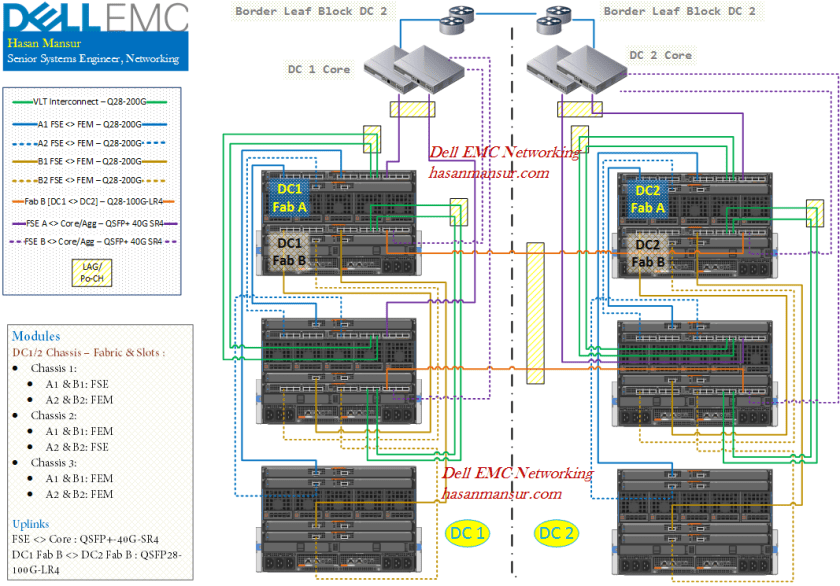
Here is an overview of the Design.
Topology Overview
- 2x DCs
- There are 3x Modular Chassis, in each DC.
- Each chassis utilizes both Fabric A and B. (So, both Server Mezzanine Slots A and B are populated). For this example, we have not populated Fabric C or depicted FC/SAS connectivity.
- Each fabric has two switching engines, one in each chassis. The other slot is filled by an Expander Module.
- Subsequent chassis will have Expander modules, in both slots, in each fabric.
- The VLT and Fabric interconnects would stay under 3 meters. This allows us to use DAC cables. Anything over 3m (and upto 20m) would require AOC.
- Fabric A is in Smart Fabric Mode. It presents uplinks to the local Core.
- For Fabric B, we are using Full Switch mode. It has 2 set of outbound links.
- First, it uplinks to its local Core.
- Second, Fabric B in DC1 is also connecting directly with Fabric B in DC2.
- the two set of links need further commentary, which follows in coming sections.
Modules & Links
This section captures the details on Switching/Expander modules, and the links.
Switching Fabric: Slot Provision
FSEs (Fabric Switching Engines) are present in lead chassis 1 and 2 (One per fabric, the other slot is populated by a FEM – Fabric Expander Modules). The third chassis (and all subsequent chassis) will be populated simply with FEMs.
- DC1:
- Lead Chassis 1:
- Fabric A:
- Slot A1 = FSE,
- Slot A2 = FEM.
- Fabric B:
- Slot B1 = FSE,
- Slot B2 = FEM
- Fabric A:
- Lead Chassis 2:
- Fabric A:
- Slot A1 = FEM,
- Slot A2 = FSE
- Fabric B:
- Slot B1 = FEM,
- Slot B2 = FSE
- Fabric A:
- Lead Chassis 1:
-
- Chassis 3:
- Fabric A:
- Slot A1 = FEM,
- Slot A2 = FEM
- Fabric B:
- Slot B1 = FEM,
- Slot B2 = FEM
- Fabric A:
- Chassis 3:
- DC2
- Exact Model is replicated in DC2.
FSE <> FEM Links
Each FEM requires one corresponding link (for now, each FEM has single uplink into each Fabric Switching Engine; This will change once Quad port NICs become available).
DC 1, Fabric A:
- Chassis 1 A1 FSE
- C2 A1 FEM
- C3 A1 FEM
- Chassis 2 A2 FSE
- C1 A2 FEM
- C3 A2 FEM
DC 1, Fabric B:
- C1 B1 FSE
- C2 B1 FEM
- C3 B1 FEM
- C2 B2 FSE
- C1 B2 FEM
- C3 B2 FEM
The exact model is replicated in DC2.
Uplinks – Physcial
In Summary,
- Fabric A in each DC, uplinks to the Core
- This is provisioned via 40G-QSFP-SR.
- 2 uplinks per FSE. So, Chassis 1 A1 FSE has 2 uplinks, Chassis 2 A2 FSE has 2 uplinks. 4 uplinks in total for Fabric A, DC 1. DC2 identical
- Fabric B in each DC, interconnects with each other. It also uplinks to the local Core switches.
- The link between Fabric B in DC1 and DC2, is provisioned via 100G-Q28-LR4.
- The uplink to the Core is presented via 40G-QSFP-SR.
- No breakout cables have been used.
Design Considerations
In this section, we will discuss some of the considerations and options for the depicted design.
Choosing Switch Operating Mode – Smart Fabric Vs. Full Switch
Both Fabric A & B uplink to their local Core switches.
Fabric A is in Smart Fabric Mode, which enables Automation & ease of Administration. It presents its Core uplinks as LACP LAGs. Fabric B on the other hand is in Full Switch mode. We have chosen to present its links to the Core, as L3. The use of Full Switch mode in Fabric B, allows us to do a number of things.
- There are certain VLANs [Group_Y] within the modular infrastructure, which we are looking to stretch between Fabric Bs in each DC. In other words, we are looking for Layer 2 adjacency/Stretched L2 Network with these Vlans, from Fabric B in DC1 to Fabric B in DC2. We do not want to consume uplinks to Core, to move this traffic between the two sites. Group Y VLANs are contained within the modular infrastructure, and not presented as routable on northbound uplinks. Now, a Smart Fabric cannot uplink/link directly with another Smart Fabric, and must go through a Proper/Full Switch. Since DC 1 Fab B connects directly with DC2 Fabric B, it means we cannot use Smart Fabric Mode in Fabric B. Do note we are have not talked about using VXLAN to tunnel the L2 traffic, we are only talking stretched VLANs.
- Second, it has enabled us to uplink to the Core via Layer 3/Routed uplinks. If we used Smart Fabric, we would be restricted to L2 LACP LAGs only. On the L3 uplinks to the Core, we can use a routing protocol & ECMP to provide convergence and L3 multi-pathing. Think of Fabric B FSEs as Two Leaf switches in an L3 Leaf and Spine topology. We have another set of VLANs, [Group_Z] which terminate on the leaf, i.e have their SVIs hosted on the Leaf. These Group_Z Vlans are distinct subnets in each DC, unlike Group_Y vlans which were the same subnet in both DCs. Group_Z VLANs are not present on the Fabric B interconnect between DC1 and DC2.
We could also uplink to the Core from the Full Switch Fabric B, via Layer 2 links. But we have to be more diligent & careful with the topology.

Uplinks to Core Network
Buffers
- When uplinking to a Core switch with shared buffers (vs. port buffers) for e.g. Z-Series, Cisco Nexus 95xx – each uplink from an FSE should preferably terminate on a port on a different tile of shared buffers. For e.g.
- FSE A1 in Chassis 1 is presenting two uplinks to Core. FSE A2 in Chassis 2 is identical.
- On each Core switch, have the 2 uplinks terminate on ports which do not share buffers.
Smart Fabric Uplinks
- Switches in Smart Fabric cannot link to another smart fabric. However, they can connect to switches in full switch mode.
- In Smart Fabric Mode, LACP is needed on upstream switches.
Multiple Uplink LAGs to different Aggregation switches
Both Smart Fabric and Full Switch mode should allow multiple uplinks i.e. multiple LAGs/Port-Channels terminating on distinct aggregation switches.
Embedded ToR
The use of MX9116 also makes available the option, to utilize the Embedded ToR function, if needed in the future.
Embedded ToR is a capability which allows the MX9116 Fabric Switching Engines, to function as Aggregation switches for Rack Servers & Storage as well. FSEs keep the communication between all these pieces – Rack Servers, Modular infrastructure and Storage, local. The FSEs can then uplink into the Core, and present traffic from all these southbound entities, into the Core.
Embedded ToR Functionality is already present, and requires no activation. Currently, it is only supported in Full Switch mode. SmartFabric mode will be supported in a future OME- Modular release.
Choosing Switch Models – MX9116 Vs. MX5108
Scalable Fabric
Both Fabric A and B in each DC, employ Scalable Fabric. this is regardless of their mode being Smart or Full Switch. If we had used MX5108 instead of MX9116 with this design, a Scalable fabric would not have been possible. Scalable Fabric is not applicable to MX5108.
Operating Mode
MX5108 would only have supported Smart Fabric Mode in a Single Chassis Solution. Smart Fabric in a Multi-Chassis Solution, like we have with Fabric A in each DC, is only supported with MX9116.
—————————————————————————
In the next post, I will conclude with some final considerations and caveats concerning MX7000 Networking.
